General Information
-
Resolution: 256 x 192 pixels.
-
Signal: Analog CVBS, USB.
-
Power supply: 5V
-
Field of view: 50° (horizontal), 37.2° (vertical).
-
Pixel size: 12 μm.
-
Wavelength range: 8-14 μm.
-
Operating temperature range: -20°C to +60°C.
Camera Integration Capabilities with Flight Controller
The thermal imaging camera supports connection to the flight controller via UART and is compatible with the Mavlink protocol for receiving AUX commands.
This enables the configuration of camera settings directly from the pilot’s control unit. The following parameters can be controlled:
-
Switching camera operating profiles
-
Automatic or manual shutter control
-
Image brightness
-
Image contrast
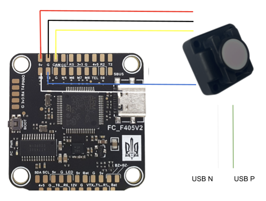
Connection Diagram
Make sure that the provided ribbon cable matches the pinout shown in the image.
|

Connection Diagram to the UAV Using Vyriy as an Example
Configuring the Appropriate UART Port
To configure the connection between the flight controller and the camera, it is necessary to activate Mavlink for the corresponding UART on the flight controller.

Channel Configuration
To configure the channel mapping, meaning to determine which function will be assigned to a specific switch, you can use Betaflight Configurator.

Enter the following command to set up a bridge between the CLI interface and the camera:
serialpassthrough X 115200
Where X is the UART number to which the camera is connected.
For example, if UART 3 is configured, enter:
serialpassthrough 2 115200
If MAVLink is not enabled?
In Betaflight versions starting from version 4.4, MAVLink telemetry is disabled. This does not apply to MilBeta, Crashdetect, Karma BF, or iNav. To change this setting during firmware flashing, specify TELEMETRY_MAVLINK in the CUSTOM DEFINES during the flashing process.

Camera Features
profile
Switching between pre-configured profiles.
Example:set aux profile 6 1000 2000
image_contrast
Camera contrast control.
Example:set aux image_contrast 4 1000 2000
image_brightness
Camera brightness control.
Example:set aux image_brightness 5 1000 2000
shutter_off
Disabling automatic shutter trigger.
Example:set aux shutter_off 7 1400 2000
colormap
Switching between color modes: grayscale or color.
Example:set aux colormap 7 1700 2000
Redefining the Camera Control Channel (set aux)
For Betaflight, the first 8 channels are available for control. For iNav/Ardupilot, there are no such restrictions. By default, channel control is set to channel 7, or AUX 3. If you need to set it to another channel, follow these steps:
-
Turn on the monitor and transmitter.
-
Connect the board to Betaflight via USB cable.
-
Power the board using the battery.
-
Wait for the camera to load.
-
Go to the CLI tab in Betaflight Configurator.
-
Put the camera into routing mode by entering the following command in the CLI, where 2 is the UART number to which the camera control is connected (use -1 for Karma/Speedybee). In the example, UART 3 is used:
serialpassthrough 2 115200 -
The next command switches to CLI mode:
switch to cli mode -
Redefine the channel that the camera will listen to for profile control. In the example, channel 7 is used:
set aux profile 6 1000 2000 -
Exit CLI, disconnect USB, and turn off the power.
Working with the USB Interface
-
Connect the camera via USB (power can also be supplied through USB).
-
The system will detect it as a network interface with IP address 10.0.0.2, subnet mask 255.0.0.0, and gateway 10.0.0.1. Verify that these parameters are set exactly as specified in the network settings.
Depending on your operating system, the method of entering this information may vary, but the key is to provide these three numbers. -
Once everything is connected and the network is configured, the camera will send UDP packets containing frames to port 5000.
Each byte represents a pixel, so the total data for one frame is 256 * 192 = 49,152 bytes per frame in a single UDP packet. No compression is applied. This is not RTP, but rather a regular buffer over UDP.

To quickly view the image, you can save this buffer to a file and then convert it into an image:
ffmpeg -f rawvideo -pixel_format y8 -video_size 512x192 -i image.raw -frames:v 1 -vf "format=gray" image.bmp
or use the Pytthon code example to check the video
import socket
import cv2
import numpy as np
udp_socket = socket.socket(socket.AF_INET, socket.SOCK_DGRAM)
udp_socket.bind(('0.0.0.0', 5000))
print("Listening on UDP port 5000...")
while True:
data, _ = udp_socket.recvfrom(65536)
if len(data) == 256 * 192:
frame = np.frombuffer(data, dtype=np.uint8).reshape((192, 256))
frame_resized = cv2.resize(frame, (720, 576), interpolation=cv2.INTER_LINEAR)
cv2.imshow("Y8 Video", frame_resized)
if cv2.waitKey(1) == 27:
break
cv2.destroyAllWindows()
Camera Mounting on the Aircraft
Via the link Kurbas-256 mount , you will find 3 different camera mounting options. The camera is secured using an M3x30 bolt and an M3 locking nut, or you can apply a thread locker to the nut if it doesn't have a locking mechanism.
Ensure that the cable ribbon is connected to the bottom part of the camera when mounting.

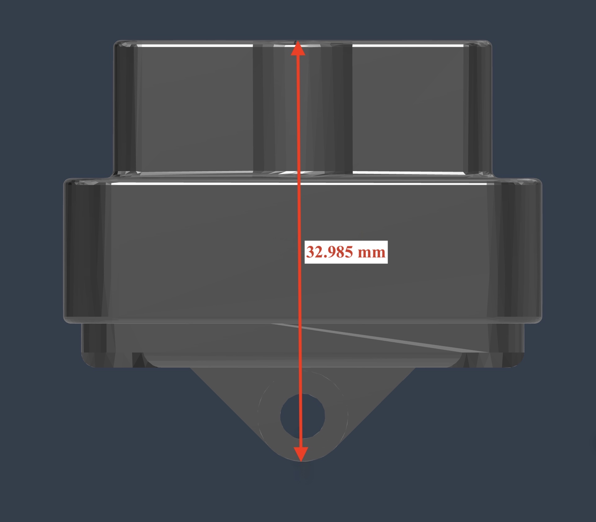
Product Dimensional Drawings
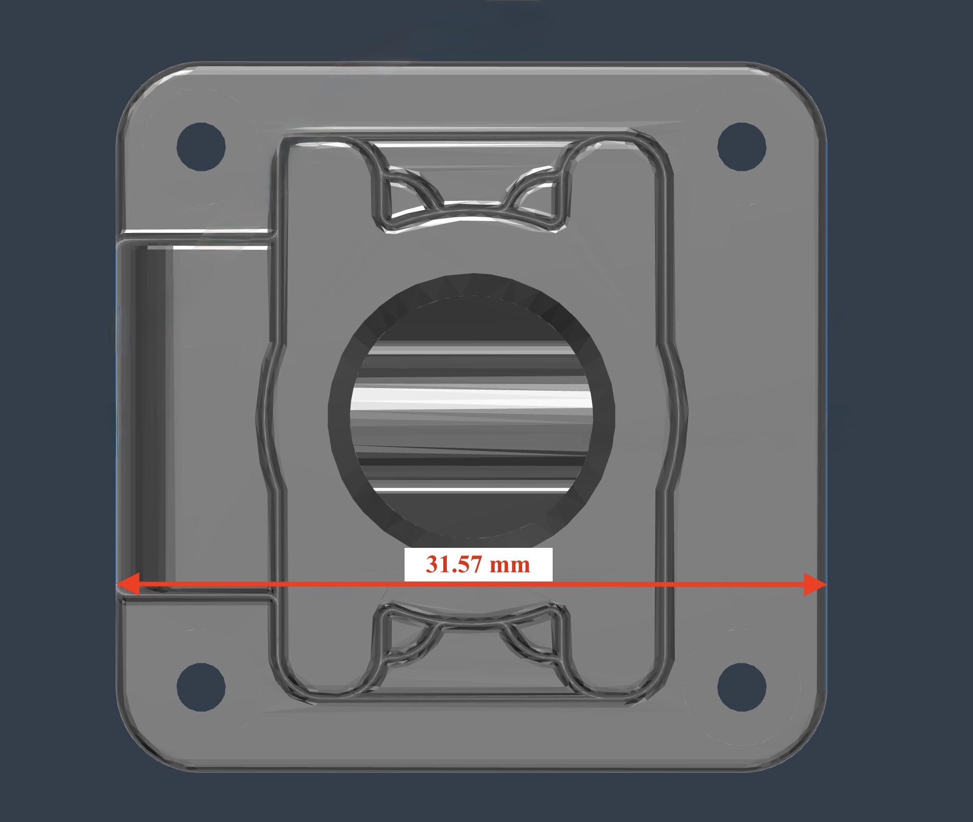
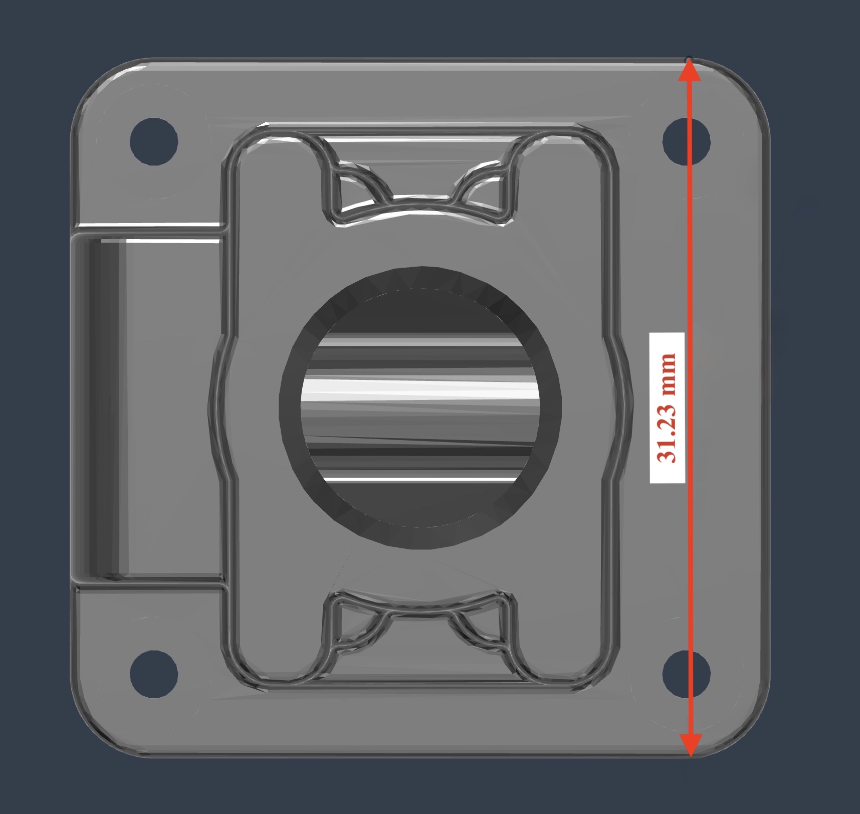
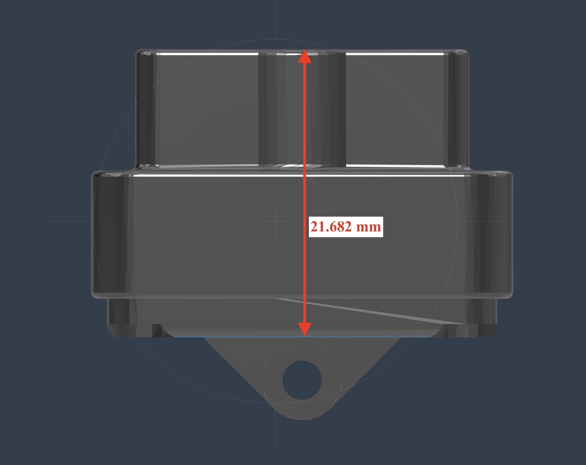.jpg)